Ship Windlass
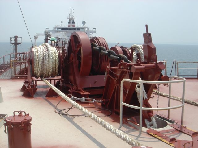
WINDLASS
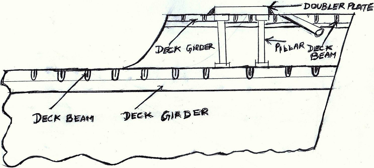
- Windlass seating:- The forces acting on the windlass when the ship is anchored is much more than the mass of the windlass and hence has to be specially strengthened , the details of which are as described under and illustrated by sketch below
- The deck plating at forecastle and main deck in forecastle space scantlings
- The windlass is mounted on a doubler plate welded to the forecastle deck
- The deck girders in forecastle space is increased in The deck beams pitch distance decreased to accommodate more beams.
- Four round pillars at four corners of the base of windlass doubler plate connect to the main deck plating to give continuity of strength to deck
The windlass machinery is combined with the forward mooring winch as one unit. The main winch consists of a double reduction gearing arrangement to produce a ;large torque.
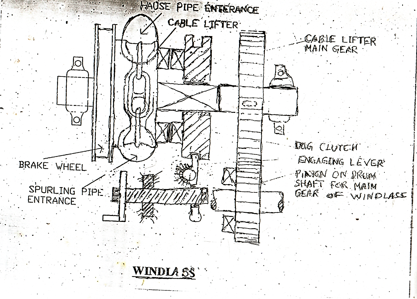
The wind lass is arranged on a further reduction arrangement.The windlass part consists of a solid cable lifter wheel combined with the brake wheel keyed to a shaft properly supported on two bearings with its clutch arrangement. The clutch connects the cable lifter to driving gear when the anchor has to be hauled up.
For anchoring purpose the clutch is released with the cable ;lifter in braked position. When the anchor has to be dropped, the brake is released and the anchor along with the chain drops by gravity so that it strikes the ground with sufficient force to get entrenched in the mud. The sketch of the wind lass part is as given under.
Ship Windlas
Electrically operated windlass
The windlass including mooring winch machinery is common for both hydraulically operated or electrically operated equipment . In the case of the electrically operated windlass cum mooring winch the driving motor is a two speed motor controlled by a suitable pole changing device. The lower speed gives higher torque suitable for the initial breaking of the anchor from the ground when more force is required and the design torque provided for this condition is 150% of the full continuous torque for a period of at least 30 minutes. All three phase induction motors are steady speed motors with a small variation of load torque. The speed is fairly high since the frequency is high and to reduce the operating speed electrically is inconvenient since it involves increasing the number of pairs of poles. To avoid this a double reduction gear box with oil lubricated machine cut gears has to be incorporated in this system. As per class rules an over load slip clutch has also to be included for safety, since electrical safety cut outs are time based and may not cut out when overload happens suddenly. For these reasons the electrically operated windlass and mooring winch has its limitations and are used only on small ships.
The electrically operated windlass is given under

Ship Windlas with mooring rope drum
Hydraulic Windlass
The hydraulically operated windlass has larger torque capacities because the hydraulic motor can operate at very low speeds even at 5 to 10 rpm, there by building a very high torque. The torque –speed characteristics of hydraulic system is much better and flexible than electrical systems. Their comparison is shown in the sketch given under
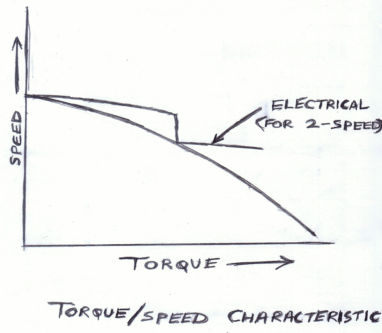
Ship Windlas torque-speed characteristics
The Hydraulic machine is robust and can withstand a lot of shock. The components are less since the double reduction gear box and the slip clutch are eliminated thereby reducing the cost of the machinery. For safety a spring loaded shock valve is provided in the system which will connect the high pressure to the low pressure side when overload occurs. The hydraulic windlass cum mooring winch is illustrated below
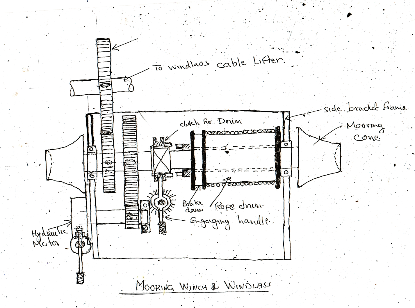 Ship Mooring winch and windlas
Hydraulic System
The hydraulic system schematic sketch below is illustrated as The main components of this system consists of the following:
- An expansion tank located on the forecastle deck to give a good head to the oil to flow
- The gear pump located in the forecastle
- The oil storage tank located in the fore castle store with attached hand pump to transfer oil to the expansion tank.
- The hydraulic motor mounted on the windlass frame and connected to the primary driving The control block is integral with the motor casing and cut sectional sketch of the motor is illustrated separately.
When the control block is placed in the neutral position the oil flow to the motor is prevented by the blanked connection in the block in this position. When the block is shifted to no 1 position only two paths are connected and the flow quantity being moderate it gives the rated speed and torque. When it is shifted to the 2nd position the oil flow has 4 paths and this conforms to the higher torque and speed rating. This position is used for breaking the anchor hold in the ground and when free the block can be used for lifting the anchor along with chain When the block is shifted to the upper R position the passages in the block are crossed causing the flow of oil in reverse direction thereby turning the motor in the reverse direction.
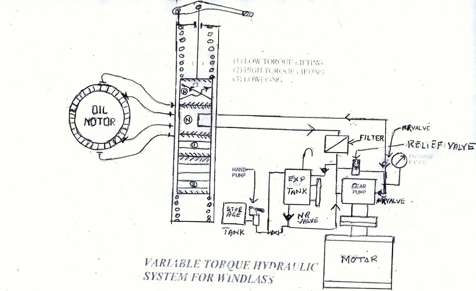
Variable torque hydraulic system for windlass
For mooring winch operations no 1 and R positions are used as convenient. For normal anchor lifting no 1 position is used. For walking back the anchor R position is used. For breaking anchor from ground no 2 position is used.
When changing over from 1 to 2 more oil is required and this is provided by oil flow from expansion tank to pump through a non return valve. When changing over from 2 to 1 excess oil from system flows back into expansion tank by another non- return valve.
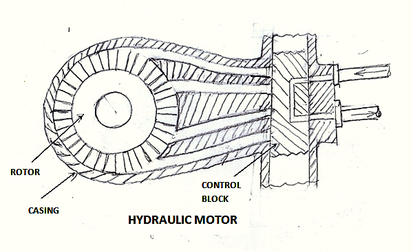
Hydraulic motor
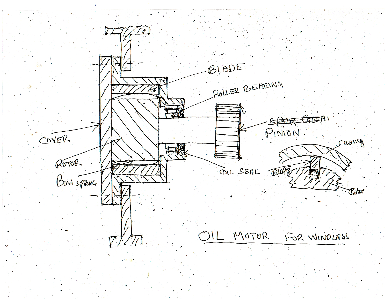
The motor is simple in construction at the same time it is robust and can take a lot of rough handling. The rotor is a thick disc with rectangular slots cut on the circumference. Each slot accommodating a thick vane held in place by the cover plate. The vanes are made to press hard on the casing (internal) surface by a bow spring held under the vane.
The rotor is mounted on a strong roller bearing and also carries an oil seal which prevents leakage of oil during operation.
Maintenance
During lay ups at special surveys, the end cover is opened up and vanes as well as springs which are damaged are renewed. The oil seal and roller bearing also renewed if they are worn out. The sketch of the winch motor with detail of vane assembly is shown under.(Fig 13b)
The electric motor driving the gear pump is a three phase double squirrel cage motor with high slip capability combined with higher rotor current capacity because of the two layers (radially) of copper bars embedded in the iron rotor. The sketch of this rotor is reproduced as under.
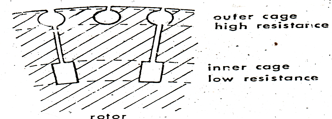
Rotor of windlass motor
Relevant important classification rules on Windlass
7.1 General
7.1.1 Windlass of sufficient power and suitable for the size of chain cable is to be fitted. Where wire ropes are proposed and approved in lieu of chain cables, suitable winches capable of controlling wire rope at all times are to be fitted.
7.1.2 Windlass is to have one cable lifter for each anchor required to be kept ready for use. The cable lifter is normally to be connected to the driving shaft by release coupling and provided with brake.
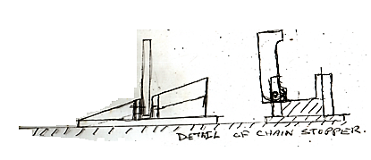
7.1.3 For each chain cable, a chain stopper is normally to be arranged between the windlass and hawse pipe. The chain cables are to reach the hawse pipe through the cable lifter only.
7.1.4 Electrically driven windlasses are to have a torque limiting device(slip clutch). Electric motors are to comply with the requirements of Pt.4, Ch.8.
7.1.5 The windlass is to be capable of exerting, for a period of 30 minutes, a continuous duty pull corresponding to the grade of chain cable, as follows :-
| 36.8 dc | for grade CC1 |
| 41.7 dc | for grade CC2 |
| 46.6 dc | for grade CC3 |
Where dc is the chain diameter [mm]. The mean hoisting speed is not to be less than 9 [m]/min.
Also See Sec. 7.2.1.
The windlass is to be also capable of exerting, for a period of not less than 2 minutes, a pull of not less than 1.5 times the continuous duty pull. The speed in this period can be lower. The above criteria do not require both anchors to be raised or lowered simultaneously on windlass fitted with two cable lifters.
7.1.6 The capacity of the windlass brake is to be sufficient for safe stopping of anchor and chain cable when paying out.The windlass with brakes engaged and release coupling isengaged is to be able to withstand static pull of 45 per cent of the tabular breaking strength of the chain without any permanent deformation of the stressed parts and without brake slip. If a chain stopper is not fitted, the windlass is to be able to withstand a static pull of 80 per cent of the tabular breaking strength of the chain without any permanent deformation of the stressed parts and without brake slip.
The chain stoppers and their attachments are to withstand a pull of 80 per cent of the tabular breaking strength of the chain without any permanent deformation of the stressed parts. The chain stoppers are to be so designed that additional bending of the individual link does not occur and the links are evenly supported.
7.1.7 Attention is to be paid to stress concentrations in keyways and other stress raisers and also to dynamic effects due to sudden starting or stopping of the prime mover or anchor chain.
(Note The rules printed in red colour are important)
I would like to request for quotation of
1 set Degicon Controller model- DPC 6S.
The controller is for the anchor windlass control valve
model – MS4 F12 6C PCKH4 120 EPD4 LS and the anchor windlass
maker is Kitagawa and model is HWD 4 2GB2W 0 H1T M
Thanks
We are from ship recycling yard in India and can offer unbeatable price for marine engines, compressors, oil purifiers and everything related to marine. New/used items & spares of renowned brands at unmatched price & immediate delivery. http://www.hementerprise.co.in, ubt60@yahoo.com, Wapp +91 9662513947
We can offer unbeatable price for recon / used refrigeration compressors of make like: Bitzer, Carrier, Copeland, Bock, Sabroe, Mycom etc, its original spares, condensers and everything related to marine from ship recycling yard in India.
Dear Sir / Madam!
Good day,
We, Thang Long Maritime JSC, Owner of M.T PVT ESTELLA IMO 9414321 and PVT DAWN, IMO 9414307.
Our vessels are installed hydraulic motors for Windlass & Mooring Winch JR-C-21U-A/JR-I-21-R-A(M1). Ser No: 34895/28551
Now, one of our vessel get problem with hyd. Motor for windlass and mooring winch as well and need spare part to renew.
We would like to send you inquiries for quotation as per request from vessel.
Kindly check and revert to us with your best quotations with full term of delivery and payment
Your good cooperation is high appreciated with many thanks