ARRANGEMENT OF DOUBLE BOTTOM & FRAMING IN MACHINERY SPACE

ARRANGEMENT OF DOUBLE BOTTOM & FRAMING IN MACHINERY SPACE
– ARRANGEMENT OF DOUBLE BOTTOM & FRAMING IN MACHINERY SPACE – A double bottom in a ship is a ship hull construction method where the bottom of the ship has two distinct layers of watertight hull floor where one of the outer layer forming the normal hull of the ship, and the inner layer forms a superfluous barrier to seawater in case the outer hull is breached.
– The space in between the two bottoms which is called as a double bottom space and is often used as storage tanks for storing fuel, ballast water, Technical Water (Non-potable).
Note: Fuel storage is not allowed since 2007 on DB tanks as regulated by MARPOL.
IMG CREDIT : BLOGSPOT.MARINENOTES.COM/CLASS4MEO
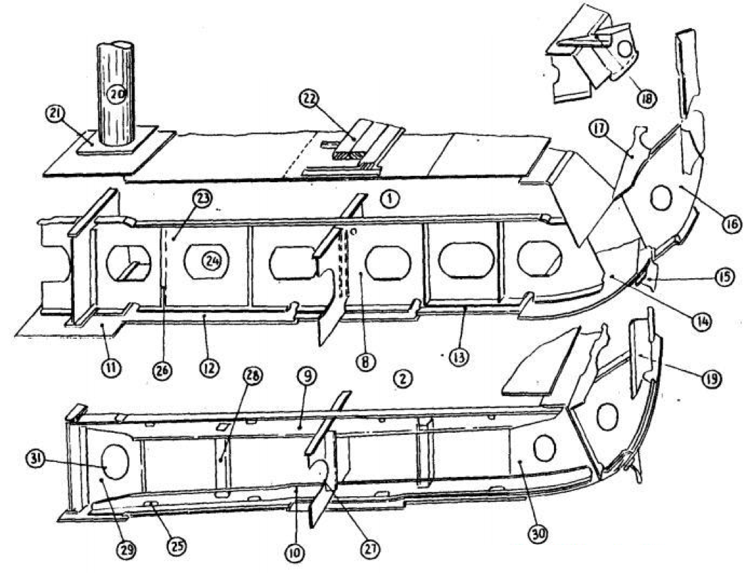
1 . Solid floor
2. Bracket floor, Open floor,Skeleton floor
3. Center girder
4. Side girder
5. Margin plate
6. Center strake
7. Inner bottom plating
8. Floor plate
9. Reverse frame
10 . Main frame
11 . Keel
12 . A trake
13 . Bottom plating
14 . Bilge strake
15 . Bilge keel
16 . Tank side bracket
17 . Gusset plate
18 . Gusset angle
19 . Hold frame
20 . Hold pillar
21 . Double plate
22 . Bottom ceiling
23 . Air hole
24 . Manhole
25 . Limber hole
26 . Vertical stiffener
27 . Vertical bar
28 . Strut
29 . Center bracket
30 . Bracket to margin plate
31 . Lightening hole
DOUBLE BOTTOM ARRANGEMENT IN MACHINERY SPACE
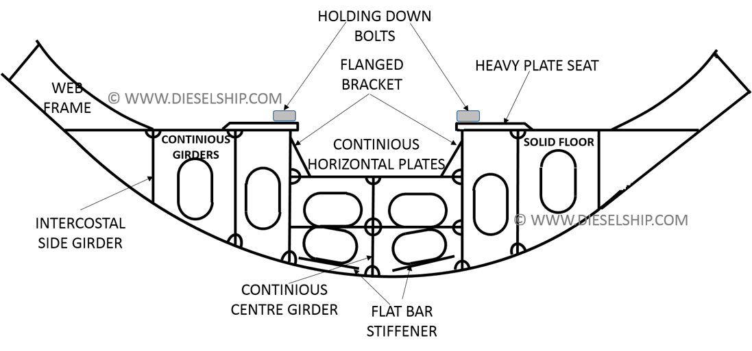
– The main engine seating are in general integral with this double bottom structure, and the inner bottom in way of the engine foundation has a substantially increased thickness of about 40mm and is continuous to the thrust block seating.– In the machinery spaces, forces of pulsating nature are transmitted through the structure due to the general out of balance forces of machinery parts, so additional transverse flows and longitudinal intercostal side girder are provided to support the machinery effectively and to ensure rigidity of the structure.
– Often the machinery is built up on seating forming longitudinal bearers which are supported transverse by tripping brackets in line with the double bottom floors, the longitudinal bearers being in line with the double bottom side girders.
– Boiler bearers are similarly fabricated with support from transverse bracket and longitudinal members.
– In motor ships, where a drain tank is required under the machinery, a cofferdam is fitted giving access to the holding down bolts and isolating the drain tank from the remainder of the double bottom tanks.
– Additional longitudinal girders are fitted in way of heavy auxiliary machinery such as generator.
Thrust block position:-
Main thrust block is placed close to the propulsion machinery in order to reduce any problem due to:-
– Deformation produced by the thrust load, which can cause misalignment problem, unless suitable sufficiently is not employed.
– Differential expansion of the shaft and hull caused due to:-
– Low hull temperature of midship engine refrigerated cargo ships, which can cause a contraction of up to 20mmrelative to the shaft whereas water temperature change or heating of fuel tanks can cause expansion of hull.
– Whirling of tail shaft, relative movement of hull and misalignment due to drop from propeller weights.
Thrust block support:-
The substantial double bottom structure under the main machinery provides an ideal foundation for the thrust block and is the reason for seating the thrust block close to the engine.


what is the source of this image? which book or…
Well explained