Plate Type Heat Exchanger
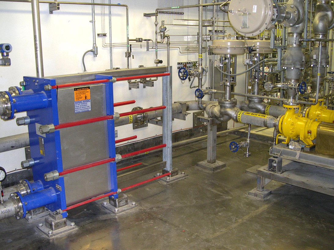
Plate type Heat Exchanger
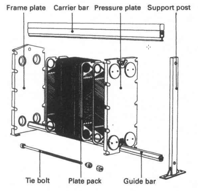
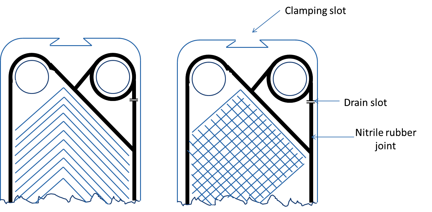
Plate type Heat Exchangers are made up from an assembly of identical metal plates pressed together. Such plates have with horizontal or chevron pattern corrugations. Each plate’s working space is protected by a nitrile rubber joint. The plates, which are supported beneath and hung at the top by metal rails on which the plates can be moved, are held together against an end plate by clamping bolts or tie bolts.
The inlet and outlet branches for each liquid are attached to one end plate. Seals around the ports are so arranged that one fluid flows in alternate passages between plates and the second fluid in the alternative passages, usually in opposite directions.
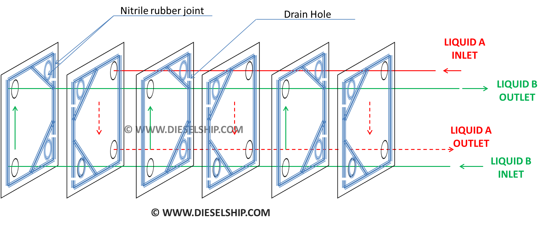
The plates have various designs of corrugations to aid heat transfer and also provide stiffness to the plates. A double seal arrangement is provided at each branch point with a drain hole to detect leakage and prevent intermixing or contamination.
The plate corrugations promote turbulence in the flow of both fluids and so encourage efficient heat transfer. Turbulence as compared to smooth flow helps more of the liquid passing between the plates to come into contact with plate. Corrugations also break up the liquid into small passages which tends to adhere to the metal and aid in efficient cooling. The corrugations make the plates stiff so permitting the use of thin material. They additionally increase plate area and both of these factors also contribute to heat exchange efficiency.
Excess turbulence, which can result in erosion of the plate material, is avoided by using moderate flow rates. However, the surfaces of plates which are exposed to sea water are liable to corrosion/erosion and suitable materials must be selected. Titanium plates although expensive, have the best resistance to corrosion/erosion. Stainless steel has also been used and other materials such as aluminium-brass. The latter may not be ideal for vessels which operate in and out of ports with polluted waters.
Plate corrugation Combinations
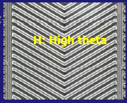
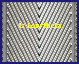
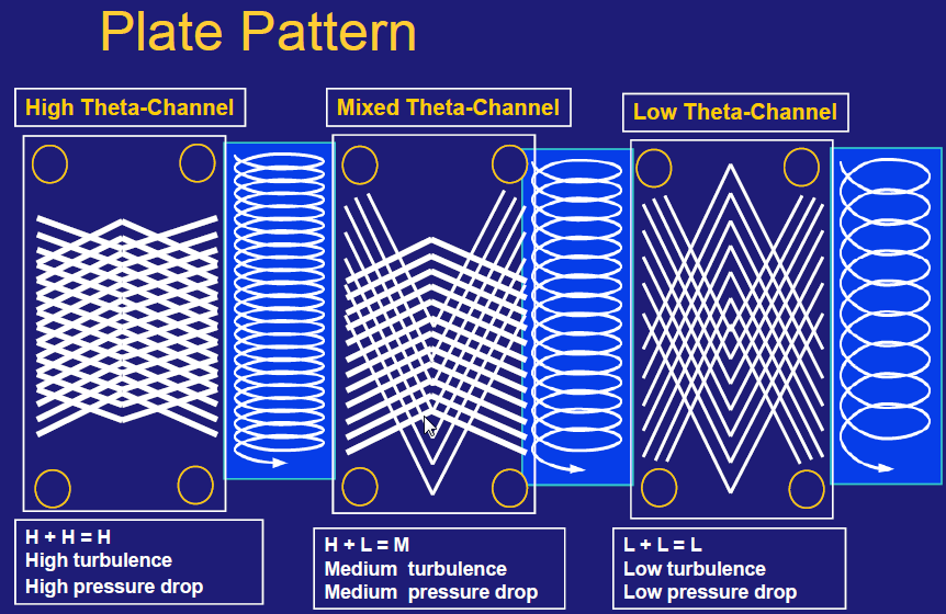
The plates have different type of possible corrugations. The angle between the corrugated channels are classified into Low theta & High theta and using plates in combination with LOW-LOW, HIGH-HIGH, LOW-HIGH-LOW, HIGH-LOW-HIGH etc offers different type of Heat transfers (Cooling).
Materials Used
Plate Materials
Plates are manufactured with number of materials and various combinations depending on the application and the operating environment. Typical plate thickness being 0.6 mm and operating pressure between 8Bar – 16 Bar while 25Bar is the maximum pressure at which such plate type coolers can be used due to the restriction in the pressure that the nitrile rubber joints can hold.
Titanium
This is a strong at the same time very light material.
Its main advantage is its super resistance to the sea water corrosion in both static & flowing conditions. But Titanium being nobler than most other metals used in the system, Cathodic titanium makes other metal in contact with it as anodic and promotes corrosion.
Stainless Steel
Stainless steel has always proved unsuccessful in plate type coolers as far as sea water operation is concerned as the elements used in SS tend to sacrifice themselves in sea water which acts as an electrolyte solution making the steel week, porus and brittle. SS plates are known to have pin holes within few years of usage.
Some successful alloys that are widely used;
- Hastalloy C276
- Nickel
- Incaloy 825
Frame which is not in contact with the liquid: Coated Mild steel
Flange connections: Aluminium, Brass or Plastic
Gasket Materials
Gaskets are fitted in the factory by bonding the material with a Thermo – Setting adhesive which is then cured in an oven.
The plates are not serviceable in the ships and are usually sent ashore for re-conditioning, Old joints are removed by applying liquid nitrogen which makes the rubber joint to become brittle which makes it easier for removal.
Nitrile Rubber:
This material is most commonly used; however it has a limiting factor of operating temperature up to 1000C.
Compressed Asbestos fiber:
Mostly used in applications where the temperature of 1000C are to be encountered then compressed asbestos fiber is used which can handle temperatures up to 2000C and to the maximum working pressure of 20-25Bar
Other materials used are Butyl rubber, Silicone, Resin cured butyl.
Working Parameters
Working pressure: 8 – 16 Bar; With asbestos joints: 16-20Bar
Working temperature: 90-1100C; with asbestos joints: 2000C
Advantage of Plate type coolers:
+ Smaller in size & lighter in construction compared to tube type coolers for the same performance.
+ Variable cooling capacity by adding / removing plates as required.
+ Less space is occupied compared to tube type cooler for the same performance and also no extra space is necessary for maintenance and other operations.
+ Simpler for cleaning and maintenance.
+ Turbulent flow helps reduce deposits; By having a back wash valve the flow is alternated to remove any sediments occurred by prolonged one direction flow.
+ Mixing of fluids is less unless if there is any crack on the plate which is highly unlikely.
+ Variable flow velocities and higher velocity flow is also possible when compared to a tube type cooler.
Dis-Advantages of Plate type coolers
– High degree of cleaning is required when assembling as entrapment of dirt on the rubber seal can easily lead to leak, proper tightening and procedures to be followed.
– Joints usually deteriorate in prolonged usage and it is very difficult to remove & repair onboard.
– Expensive due to cost of titanium plates & joints.
– Plates are damaged and joints deformed easily due to over tightening or improper tightening procedure.
FLOW PATTERNS USED IN PLATE TYPE COOLERS
Parallel Flow
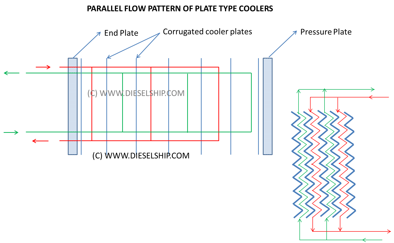
– In general for a normal heat transfer requirement the plates are assembled in parallel as shown in the picture to effect a steady heat transfer. In the simplest case, the flow rate per channel needed to produce a desired temperature change in the primary fluid is determined (the fluid requiring heating or cooling) with a given size of plate and then connect to enough channels in parallel to handle the total flow volume.
– Parallel flow aids in Low turbulence, Low pressure drop across the system and hence low heat transfer.
Series Flow
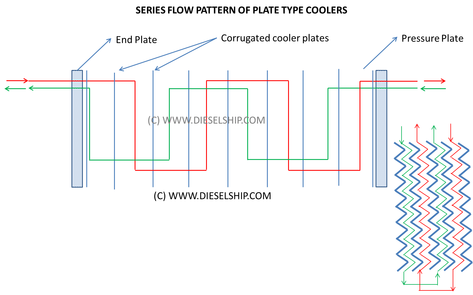
If the heat transfer required is high and where the required temperature change is too great to be accomplished in one pass, groups of Plates can be connected in series by inverting the plates to aid flow as shown on the figure.
Series flow aids in high turbulence, high pressure drop across the system and hence high heat transfer.
Credits:
Information & diagrams furnished in this article is collected from various books, presentations, manuals and from authors own experience. We would like to credit the following sources from which (not limited to) valuable information were obtained.
- Marine auxiliary machinery by H D Mc George
- Alfa-Laval website
- Alfa Laval manual

