VARIOUS SHIP PLANS REQUIRED BY SHIPYARD FOR DRY DOCKING
VARIOUS SHIP PLANS REQUIRED BY SHIPYARD FOR DRY DOCKING
VARIOUS SHIP PLANS REQUIRED FOR DRY DOCKING :-
The following plans and drawings are required to be submitted to the shipyard for their use to enable the ship to be dry docked safely. To be submitted before ship enters dry dock
(1) G.A. plan (a reduced copy would do )
(2) Docking plan- ( Fig.1)
(3) Capacity plan with D.wt and displacement /draft scale. After ship has docked.
(4) Shell Expansion. (Fig.2)
(5) Mid-ship Section For structural repairs as ordered.
(6) Detailed location plans of areas where repairs and renewals are required. For propeller shaft withdrawal and survey if ordered.
(7) Assembly drawing of propeller shaft ,propeller and stern tube.
(1)G.A Plan
The General arrangement plan gives a profile view of the ship along with plan views at main deck level, and D.B. tank top level, and an end view from forward. This drawing is used for berthing purposes alongside repair berths as well as to get a general appearance of the ship. Hence a reduced size drawing would do.
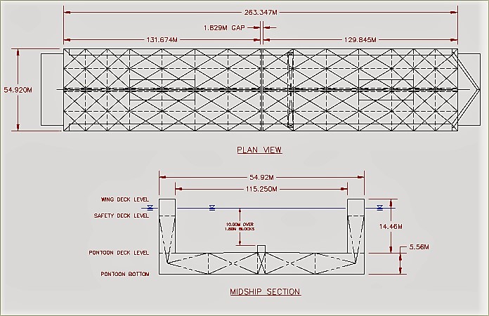
(2) Docking plan
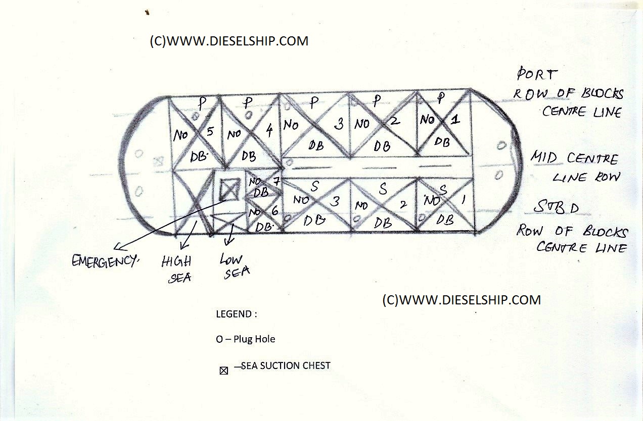
Docking Plan
The docking plan is a detailed plan view seen from the bottom. It shows all openings on the bottom , including the openings for the main sea suction boxes provided at the machinery room area on the under side . The other openings are the individual drain plug holes normally one plug hole per tank . In large ships tanks may be provided with two holes per tank. The plan also shows the recommended lines for block laying with recommended pitch of the blocks . Normally three rows of blocks are sufficient to safely support bulkers tankers and container ships. For cargo ships with finer form locations for the fitting of Breast shores are shown in the plan.
It should be understood that this docking plan is to be used only for normal dry docking purposes. In the case of ships being dry docked after heavy collision or bottom damage, this docking plan will not be suitable. For this purpose an amended docking plan is made after the ships bottom is photographed in afloat condition by the shipyard diver and an amended plan made to suit the purpose. It must provide for alternate locations of support for the damaged area where the original blocks cannot be laid for support.
(3)Shell Expansion
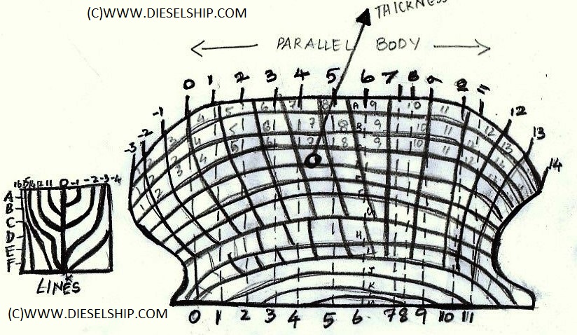
Shell Expansion Plan
It is a two dimensional drawing of a three dimensional surface of the ship’s hull form. It is developed from the ship’s line plan with the contour lines erected straight on the base line representing the ship’s length. The contour lines on the lines plan are located at corresponding stations indicated by corresponding frame numbers on the length of the base line. When the ends of the vertical lines on the baseline are joined by a continuous line , the shell expansion outline is obtained. The represented surface is then properly marked by parallel lines both vertical and horizontal lines so that they correspond exactly to the number of strakes forming one half of the hull surface. The strakes are marked with letters A,B,C ,etc vertically starting from sheer strake as strake A and ending with keel as strake R eg. The strake numbers are staring from 1 at the stern end to any ending number at the forward bow. Each strake is there fore indicated by a letter to show its level , a number to show its position.
This plan is very useful for the following information:
(a) It is used for marking the location of a hull Damage on this plan by identifying the strake number , letter and frame number so that the exact location of the damage and also suggested repairs are marked in a localised copy.
(b)The shell expansion can be used for finding areas of painting surfaces such as topside, boot topping and bottom areas by applying Simpsons rules directly. In the shell expansion the vertical scale used is different from the horizontal scale and a suitable adjustment has to be made when calculating areas.This becomes useful in solving disputes concerning areas of preparation and painting.
(c) It gives information on the thickness of the original strake which is indicated by the number in the circle shown in the strake. The quality of steel used is also shown by letters A,B,D E and AH, BH,DH, EH.
(4) Capacity plan
This plan is useful in finding the displacement of the ship for a selected mean draft. The Displacement is required to be known to decide on the total number of blocks to be used since each block can support only a maximum given mass. The capacity plan also gives information on
(a) volumes of compartments/tanks in M3
(b) location of centre of volume of compartment/tank
Hence the capacity plan may be used for making minor stability calculations for moments which are required for trim and heel adjustments.
Useful and educative article. Thank you for the post.
Useful abd educative article.
Shell expansion strake naming starts from keel .