Hydraulic Governor for Marine diesel engine
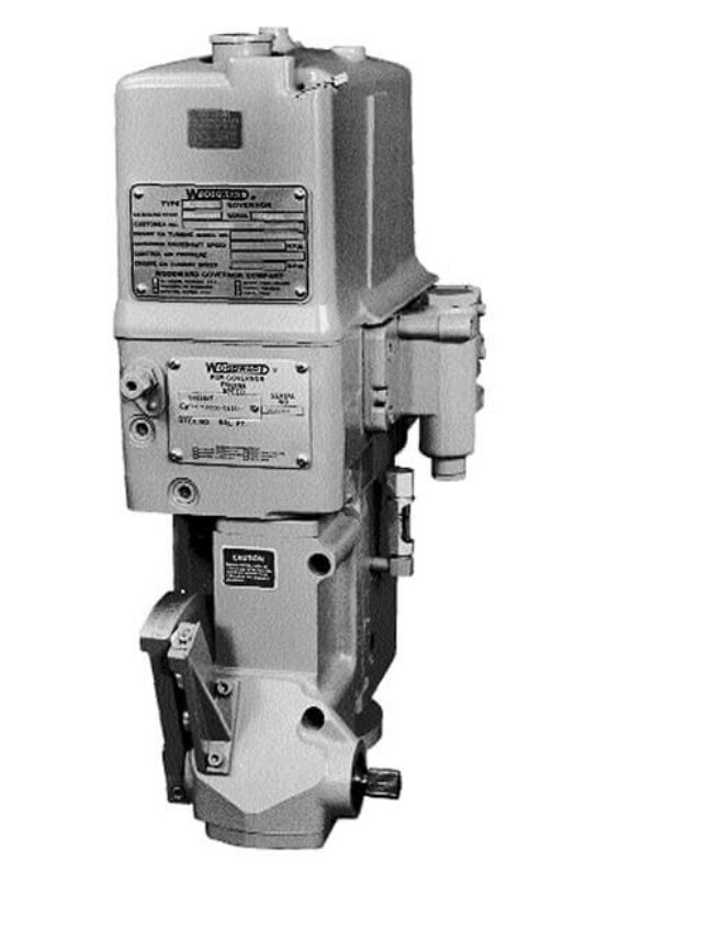
Hydraulic Governor Working Principle & Operation
A Comprehensive Guide Based on the Woodward PGA Governor
1. Introduction to the Hydraulic Governor
The hydraulic governor is a critical control mechanism utilized to regulate the speed and power output of prime movers[cite: 5]. Widely applied in marine propulsion, power generation[cite: 5]. The governor ensures that an engine maintains a steady state or responds accurately to variable load demands. The PGA model, specifically, is a pressure-compensated, hydraulic governor that relies on an air signal to establish its internal engine speed setting[cite: 3, 23].
2. Core Working Principle
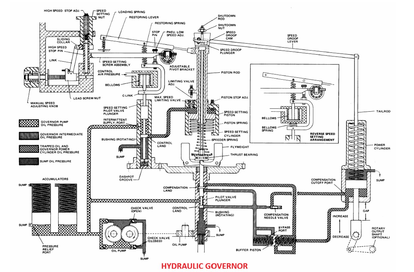
At its heart, the hydraulic governor operates by regulating fluid pressure to drive mechanical actuation. The operational sequence depends on a carefully orchestrated interaction between hydraulic forces and centrifugal mechanisms:
- Hydraulic Supply: The governor features an internal oil pump, a relief-valve, and an accumulator system[cite: 24]. Together, these components precisely control the governor's operating pressure[cite: 24].
- Self-Contained Sump: To prevent contamination from external sources, the governor utilizes a self-contained sump that stores the lubricating oil [cite: 25] (typically SAE 10 to 50, depending on the operating temperature [cite: 139]).
- Flow Control: Oil flow to and from the power cylinder (servomotor) is dictated by a centrifugal flyweight and pilot-valve assembly[cite: 26]. Changes in engine speed alter the centrifugal force on the flyweights, which shifts the pilot valve and modifies the hydraulic pressure.
- Power Actuation: The power cylinder uses this directed hydraulic pressure to position the engine's fuel racks, fuel valve, or steam valve, effectively increasing or decreasing the fuel supply to correct the speed error[cite: 27].
3. Speed Setting and Operation
The operational versatility of the governor allows for both manual and pneumatic speed adjustments, making it adaptable to complex industrial and marine environments.
Pneumatic Operation
A standard PGA governor employs a pneumatic speed setting mechanism[cite: 9, 19]. A pneumatic signal (control air pressure) operates a bellows system—configured either as direct or reverse acting—to continuously alter the engine's speed setting[cite: 28, 139]. Standard systems operate on a 690 kPa (100 psi) threshold, though higher-pressure configurations of 1379 kPa (200 psi) are available as an option[cite: 10]. This air-based signal ensures that the governor is economical to install and straightforward to maintain[cite: 7].
Manual Adjustment and Stability
In scenarios requiring direct human intervention, a manual speed adjustment knob is located on the governor unit[cite: 29]. Once the speed is set, the governor employs an adjustable compensation system[cite: 29]. This system acts as a stabilizing feedback loop, preventing the engine from hunting or oscillating around the target speed, ensuring steady-state speed control within 0.25% of the rated speed under normal operating conditions[cite: 139].
4. Advanced Accessories and Features
To meet specific operational requirements, hydraulic governors are often equipped with a wide variety of limiters and safety accessories[cite: 6]:
- Heat Exchangers: A heat exchanger helps maintain governor temperature below 200°F, preserving the internal oil[cite: 34].
- Shutdown Devices: Crucial for engine protection, these devices can be triggered by low lubricating oil pressure, or extreme air, oil, or water pressure conditions[cite: 36]. An energize or de-energize solenoid shutdown device is also available[cite: 37].
- Booster Servomotor: Mounted externally, this uses start air to supply immediate oil pressure to the governor as an aid for quick starts[cite: 38, 39].
- Fuel and Torque Limiters: These include Starting Fuel Limiters (limits fuel flow to the engine during starting [cite: 41]), Air Pressure Fuel Limiters (reduces smoke and improves efficiency during acceleration as a function of manifold air pressure [cite: 43, 44]), and Torque Limit Controls (limits fuel as a function of engine speed [cite: 51]).
- Load Control: Predominantly used in many marine applications, this system provides a definite fuel or governor output position for each specific governor speed setting and in turn controls the engine power output[cite: 46, 47].