

Complete Guide to Cylinder Liner Calibration in Marine Engines

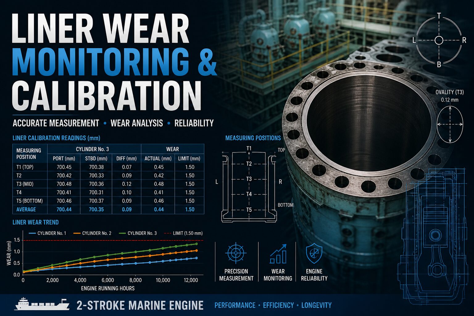
Cylinder Liner Calibration: Measuring, Recording, and Interpreting Wear
1. Key Metrics & Operational Baselines
Cylinder liner calibration is a highly critical maintenance routine aboard merchant vessels. Over time, the continuous sliding friction of piston rings combined with the corrosive environment of burning residual fuels gradually wears down the inner surface of the cylinder liner. Regular, precise calibration helps engineers predict component lifespan and prevent catastrophic engine failure.
2. Preparation & Tooling
Correct calibration requires exact tooling supplied by the engine manufacturer to ensure measurements are repeatable across different overhauls.
Calibration Template
A metal strip or template featuring strategically positioned holes corresponding to the required vertical measurement depths (Positions 1 through 6).
Micrometer & Extension
An inside micrometer fitted with extension bars. Must be rigorously calibrated against a master gauge (trammel) before insertion through the template holes.
Thermal Matching
The liner should ideally be cold. If warm, the gauge must be brought to the same ambient temperature to cancel out thermal expansion discrepancies.
3. Standard Execution Procedure
The 11-step execution procedure must be strictly followed in accordance with Maker's instructions and Lock-Out/Tag-Out (LOTO) safety protocols.
Phase A: Isolate & Prepare
- 01. Isolate: Cool engine, drain jacket water, open indicator cocks, engage turning gear.
- 02. Dismantle: Remove cylinder head and safely extract the piston using lifting tools.
- 03. Cover Box: Securely cover the stuffing box to prevent debris entering crankcase.
- 04. Anti-Polishing: Remove the top anti-polishing ring (if fitted).
Phase B: Inspect & Correct
- 05. Place Ladder: Lower and secure the inspection ladder inside the unit.
- 06. Clean: Thoroughly wipe down the liner wall for accurate surface contact.
- 07. Temp Correction: If tool and liner temps differ, calculate and apply the correction factor.
Phase C: Measure & Record
- 08. Insert Template: Hang the calibration template from the top of the liner.
- 09. Gauge Axes: Take readings in Port-Stbd and Fwd-Aft directions at all holes.
- 10. Assess Patterns: Check specifically for ovality and top 1/3 wear.
- 11. Baseline: Record in the tabular report form and calculate final running rate.
4. Measurement Axes & Wear Phenomena
Readings are always taken in two perpendicular directions: Forward-Aft (F-A) and Port-Starboard (P-S). Because the piston thrust side acts heavily on the Port and Starboard walls during the power stroke (due to connecting rod angularity), wear is usually greater on the P-S axis, leading to liner ovality.
Top 1/3 Wear Phenomenon
The wear rate is not uniform along the length of the cylinder. Material loss is always maximized near Top Dead Center (TDC), corresponding to Positions 1 and 2 on the calibration template. This is caused by the extreme combustion temperatures burning away lubricating oil film, resulting in boundary lubrication and localized acid dew point corrosion.
| Vertical Position | Typical Wear Profile (mm) | Wear Zone Characteristic |
|---|---|---|
| Pos 1 (Top Dead Center) | 0.85 mm | Highest wear. Intense heat, high pressure, acid corrosion. |
| Pos 2 | 0.60 mm | Heavy wear. Transition out of combustion zone. |
| Pos 3 (Mid-stroke) | 0.25 mm | Moderate wear. Good hydrodynamic lubrication established. |
| Pos 4 | 0.15 mm | Light wear. Lower temperatures and pressure. |
| Pos 5 | 0.10 mm | Minimal wear. Near scavenge ports. |
| Pos 6 (Bottom) | 0.05 mm | Negligible wear. Maximum oil film thickness. |
5. Key Calculations
Ovality = | (Port-Starboard Reading) - (Forward-Aft Reading) | This calculation is performed at each vertical position. High ovality indicates uneven loading, potential ring sticking, or guide shoe misalignment.
Rate = (Current Max Reading - Previous Max Reading) / Running Hours between surveys If the wear rate increases sharply, it serves as an early warning for engine overload, incorrect cylinder oil feed rates, or high cat-fines in the fuel.
6. Official Cylinder Liner Gauging Report Form
All measurements must be permanently recorded on an official report form to maintain a historical interpretation of engine wear. A standard template layout is provided below:
Cylinder Liner Gauging Report Form
| Cylinder Number | Date | ||||||||||
| Date cyl. installed | Date of last gauging | ||||||||||
| Total Hours | Hours since last gauging | ||||||||||
| Position | Port & Starboard | Forward & Aft | |||||||||
| 1 | |||||||||||
| 2 | |||||||||||
| 3 | |||||||||||
| 4 | |||||||||||
| 5 | |||||||||||
| 6 | |||||||||||
| Maximum Wear | |||||||||||
| Ovality | |||||||||||
| Mean Max wear | |||||||||||
| Wear rate since installation | |||||||||||
| Wear rate since last gauging | |||||||||||
| Remarks: | |||||||||||
Visual Aid for Marine Engineering Maintenance & Safety Procedures.