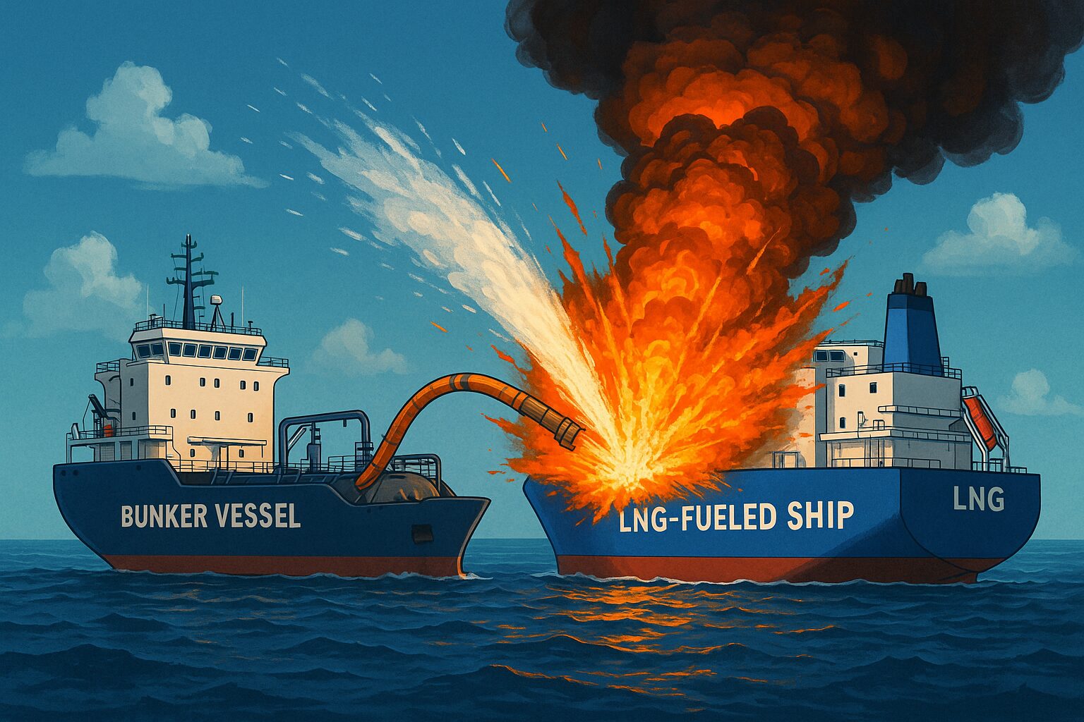
Operational Dynamics and Safety Protocols in LNG Bunkering: A Technical Analysis of Gassing Up, Cooling Down, Vapour Management, and Emergency Release Systems

LNG Bunkering Operations
Interactive technical analysis of Gassing Up, Cooling Down, Vapour Management, and the critical Emergency Release Coupling (ERC) protocols.
Gassing Up (Inert to Natural Gas)
Gassing up is the transition from an inert condition (Tank filled with N₂, O₂ < 2%) to a warm natural gas condition. It is impossible to introduce liquid LNG directly into an inerted tank because the CO₂ in the inert gas would freeze and block valves. Furthermore, mixing LNG directly with air is explosive; thus, N₂ is used as a buffer.
[Image of LNG gassing up diagram]Operational Methods
Method A: Piston Flow (Displacement)
Inject LNG vapour at the top (lighter) to push heavy Inert Gas (N₂/CO₂) out the bottom.
Best for: Cylindrical tanks (Type C) to minimize mixing.
Method B: Dilution (Mixing)
Pressurize with LNG vapour, mix, and vent. Repeat until limits are met.
Best for: Complex tank geometries (Membrane/Prismatic).
Target Criteria
- Oxygen (O₂): Must remain < 2% (ideally 0%) throughout.
- CO₂: Must be removed to < 0.1% to prevent freezing.
- Methane (CH₄): Target > 98% (Warm Natural Gas state).
- Dew Point: Must be lowered to prevent moisture freezing.
Atmosphere Transition Chart
Visualizing the displacement of N₂ by CH₄ over time.
Cooling Down (Warm Gas to Cryogenic)
Once the tank contains Warm Natural Gas, it must be cooled to approx -130°C to -160°C before bulk liquid transfer begins. This prevents excessive thermal stress (shock) on the tank material (stainless steel, invar, or aluminium) and prevents the rapid generation of boil-off gas (flash evaporation).
Detailed Procedure
Spray Injection
Liquid LNG is introduced via spray nozzles (atomizers) at the tank top.
Controlled Evaporation
The liquid absorbs latent heat from the tank walls and evaporates, cooling the steel.
Cold Spot Inspection
Crew checks deck and manifold flanges for icing or leaks (indicates seal failure due to contraction).
Critical Limit: Thermal Gradient
The vertical temperature difference (Top vs Bottom) must not exceed manufacturer limits (e.g., 30-50°C difference) to prevent structural warping.
Thermal Descent Profile
Maintaining cool-down rate < 10°C/hour average.
Vapour Management & Pressure Control
During bunkering, liquid LNG entering the tank displaces existing vapour and creates new vapour via "flashing" (Boil-Off Gas or BOG). If this vapour is not managed, tank pressure will rise rapidly, leading to safety valve lift (venting to atmosphere), which is environmentally prohibited and dangerous.
Management Strategies
1. Vapour Return Line (VRL)
Connecting a hose to send BOG back to the bunker vessel.
Free Flow: If bunker vessel tank pressure is lower.
Assisted: Using a Vapour Return Pump if resistance is high.
2. In-Tank Condensation
Spraying sub-cooled liquid LNG into the vapour space (top spray) to re-condense BOG, lowering pressure without returning it.
3. Consumption
Directing excess BOG to the ship's boilers, Gas Combustion Unit (GCU), or dual-fuel generators during the operation.
Pressure Limits
- Operating: 0.1 to 0.7 bar (gauge)
- High Alarm: 90% of MARVS
- Trip/Vent: 100% MARVS (e.g. 4.0 bar type C)
Pressure vs Transfer Rate
Higher flow = Higher pressure generation.
ERC (Emergency Release Coupling) & ESD
The ERC is part of the Emergency Shutdown (ESD) system. It is a "dry-break" coupling installed on the transfer hose/arm. Its function is to physically disconnect the hose safely (without spillage) if the vessel drifts out of position or if a catastrophic event occurs.
The Two-Stage Logic
ESD-1 (Emergency Shutdown)
Trigger: Gas detection, fire alarm, manual push, or initial drift limit.
Action: 1. Supply pumps STOP.
2. ESD valves (Double Block & Bleed) CLOSE.
3. Transfer halts.
Note: Physical connection remains intact.
ESD-2 (Emergency Release)
Trigger: Extreme drift (break-away limit) or manual 'ESD-2' activation.
Action: 1. Dry-break valves inside ERC close (trapping LNG).
2. Locking collar releases.
3. Hose falls away (controlled separation).
Interactive Simulation
Activate scenarios to see system response.
