

Starting air timing explained: why 15°, 130° and 115°

Starting air timing explained: why 15°, 130° and 115°
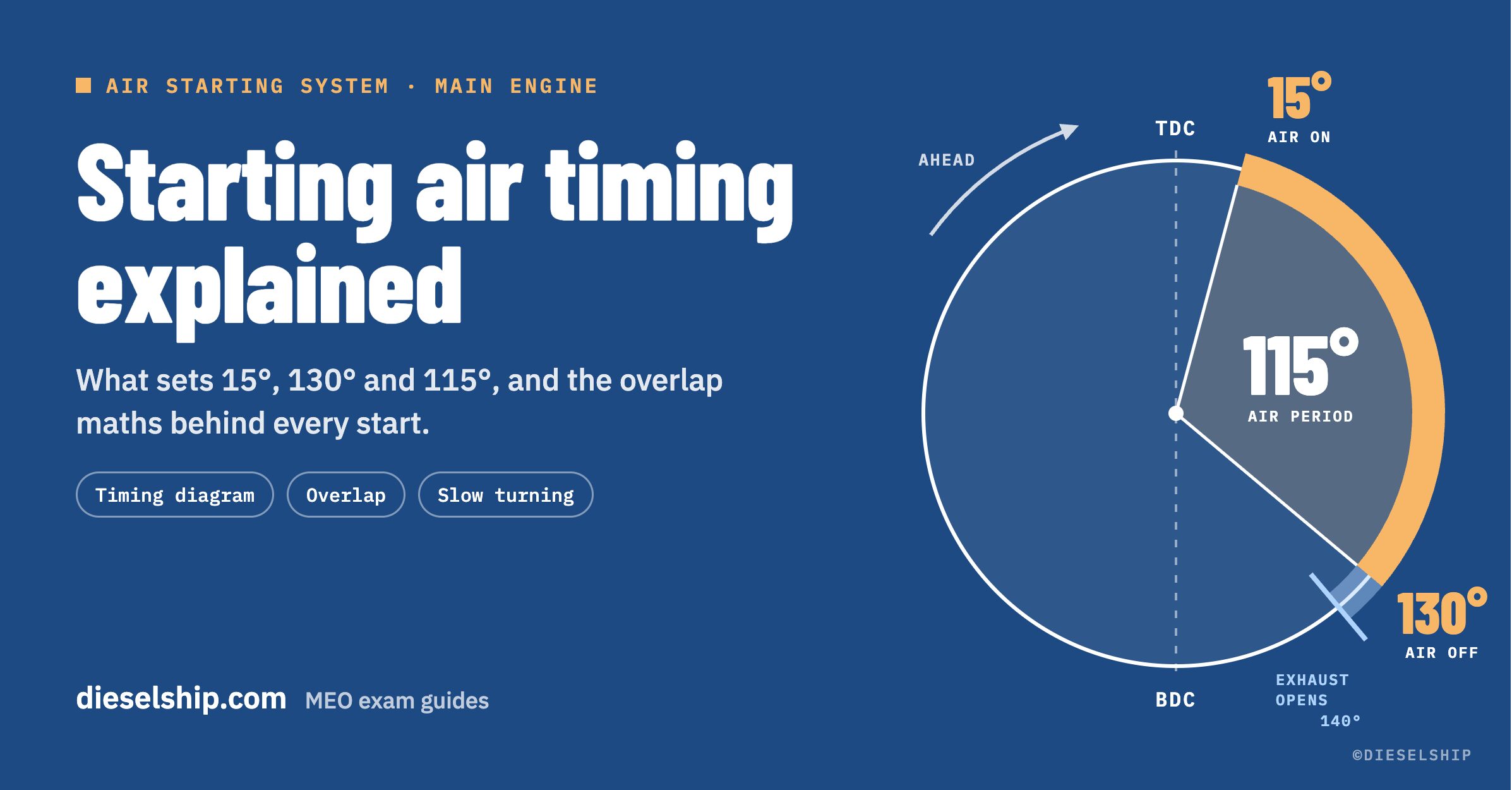
Air on at 15° after firing TDC, off at 130°, exhaust opening at 140°. What sets each angle, how the overlap between cylinders is worked out, and why a two-stroke needs at least four cylinders to start on air.
Most explanations of air starting stop at "compressed air pushes the pistons down". What decides whether the engine actually starts is the timing: when each starting air valve opens, when it closes, and how the cylinders hand over to each other. This article takes the classic diagram angle by angle and shows the arithmetic behind every number.
The timing diagram at a glance
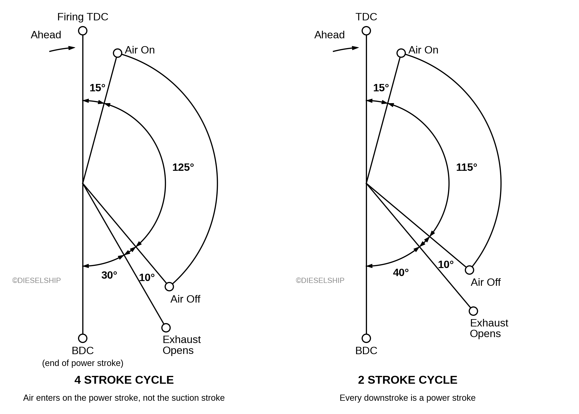
The starting air period runs from just after firing TDC to a point safely before the exhaust opens. The two-stroke and four-stroke diagrams differ only because the exhaust opens at a different crank angle.
| Event | Two-stroke | Four-stroke |
|---|---|---|
| Starting air valve opens | 15° ATDC | 15° ATDC |
| Starting air valve closes | 130° ATDC | 140° ATDC |
| Exhaust opens | 140° ATDC (40° BBDC) | 150° ATDC (30° BBDC) |
| Air period | 115° | 125° |
| Margin before the exhaust opens | 10° | 10° |
| Firing interval, n cylinders | 360° ÷ n | 720° ÷ n |
ATDC: after top dead centre. BBDC: before bottom dead centre. These are typical teaching values; the actual timing of any engine is set by its maker.
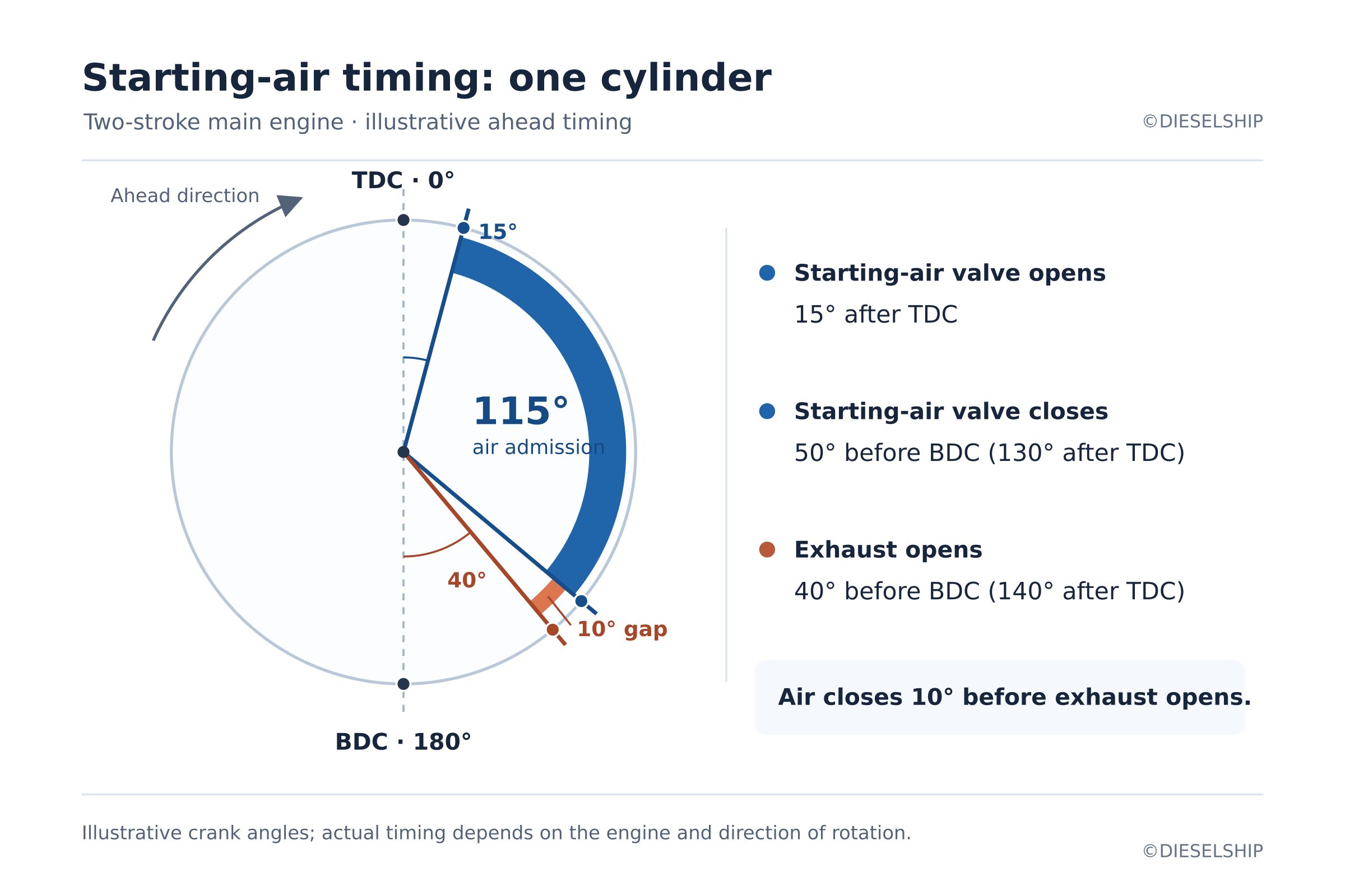
What the single-cylinder diagram must show
- TDC, BDC and the direction of rotation
- Air on at 15° ATDC and air off at 130° ATDC
- Exhaust opening at 140° ATDC (40° BBDC)
- The 115° air period and the 10° margin before the exhaust opens
- A note that it is drawn for a two-stroke main engine, with the four-stroke values for comparison
Why does the starting air valve open 15° after TDC, not at TDC?
At TDC the crank and the connecting rod are in line, so air pressure on the piston gives no turning moment. It only loads the bearings.
The turning moment depends on the lever arm: the perpendicular distance between the connecting rod's line of action and the crankshaft centre. At TDC that distance is zero. As the crank moves past TDC the lever arm grows, and by about 15° ATDC the air pressure gives a useful turning moment in the correct direction of rotation.
Air admitted before TDC acts while the piston is still rising. It pushes against the direction of rotation, so it works against the start instead of helping it.
Which TDC? The firing dead centre
A four-stroke engine passes TDC twice in every cycle. Starting air must follow the TDC at the end of the compression stroke, the firing dead centre. At the other TDC, at the end of the exhaust stroke, the exhaust and inlet valves are open and the air would blow straight through.
The valve that opens before TDC
On real engines some starting air valves are set to begin opening up to about 10° before TDC. This does not break the rule. The valve needs a few degrees of crank angle to open fully, so by the time air is really flowing the crank is past TDC. Any reverse turning moment in those first degrees is negligible, because close to TDC the lever arm is almost zero.
Why does the starting air shut off at 130°?
So that the starting air valve is closed before the exhaust opens. Air still entering after that goes straight through the cylinder to the exhaust, does no work on the piston and wastes receiver air.
In the classic two-stroke diagram the exhaust opens at 140° ATDC (40° BBDC), so closing at 130° ATDC leaves a 10° margin.
Wasted air matters because the receivers are sized for a fixed number of starts. Class rules require enough air for at least 12 consecutive starts, alternately ahead and astern, on a reversible main engine without topping up, and at least 6 on a non-reversible engine. Late air also gives less and less turning moment, because past mid-stroke the lever arm is shrinking again.
Why a four-stroke gets a longer air period
A two-stroke must open its exhaust early so that the cylinder pressure can blow down before the scavenge ports open. A four-stroke has a separate exhaust stroke, so its exhaust valve can open later, about 30° BBDC (150° ATDC). The air can then stay on until about 140° ATDC, a 125° air period.
Modern uniflow engines
On modern uniflow two-stroke engines the exhaust valve opens earlier, about 110° to 120° ATDC, so the starting air closes earlier too, about 100° to 110° ATDC. The rule is unchanged: air off before exhaust open. The shorter air period is still well above the firing interval of a six-cylinder engine (60°).
Starting air overlap: the arithmetic
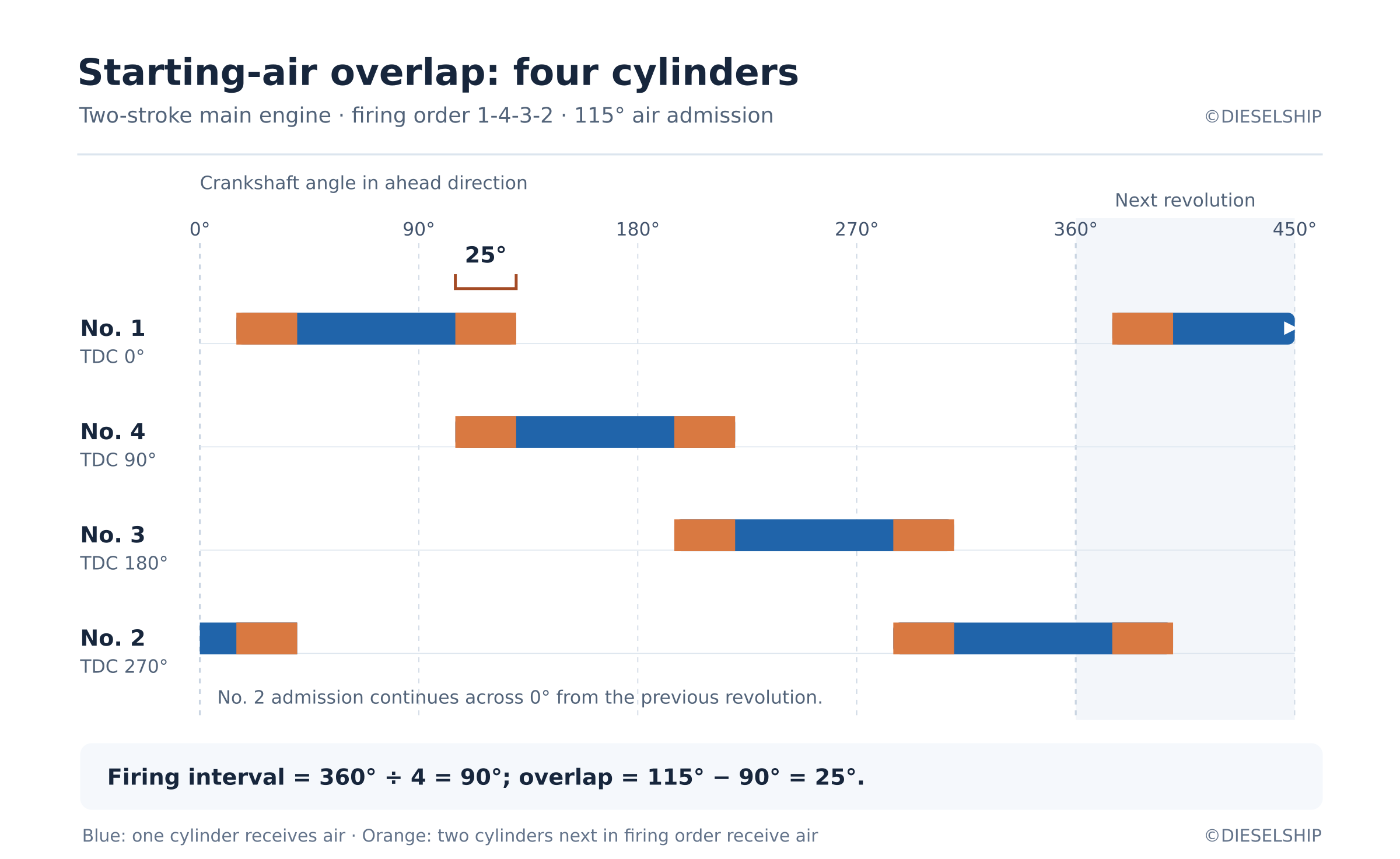
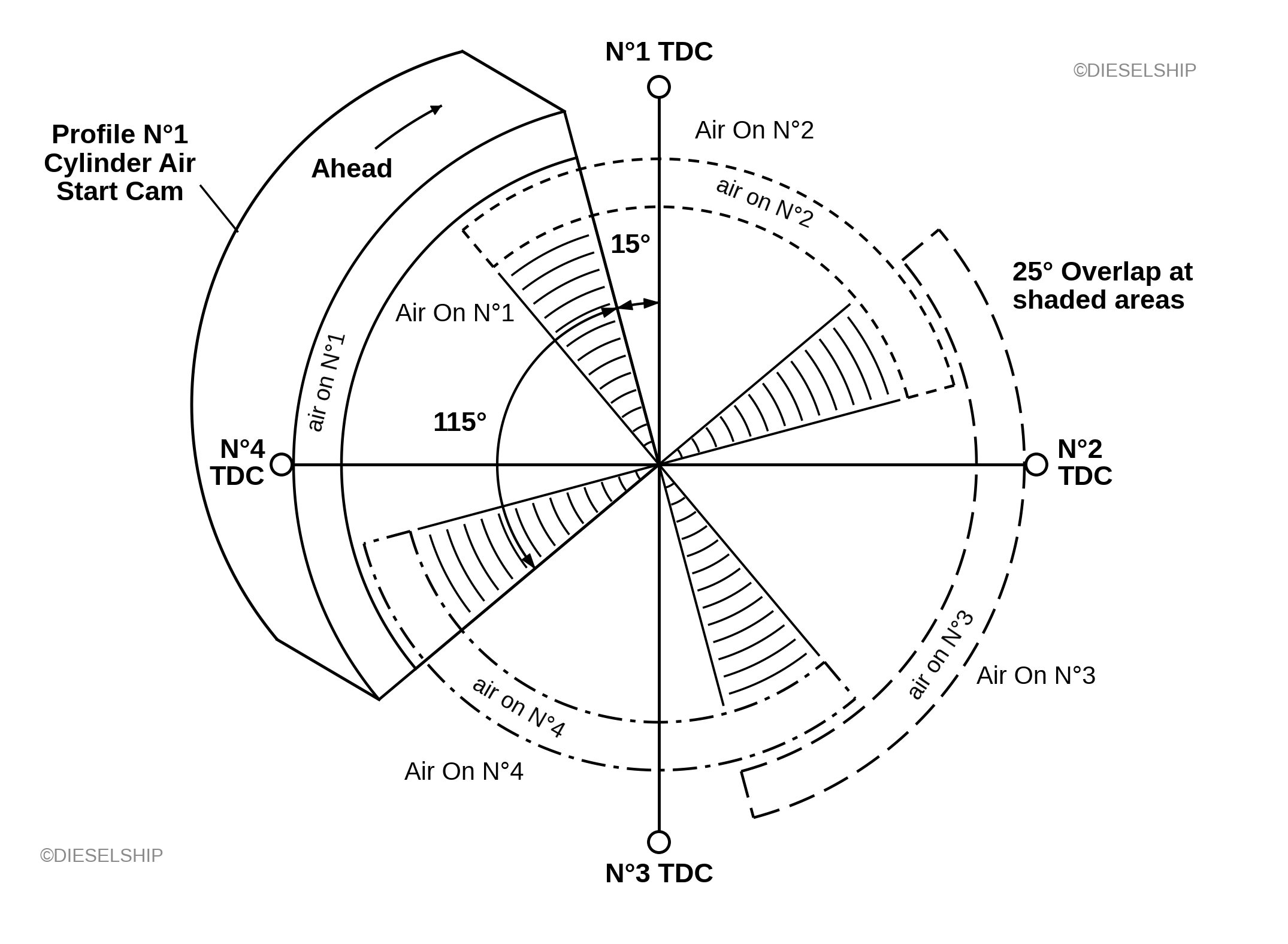
Starting air overlap is the crank angle during which the starting air valves of two cylinders, next to each other in the firing order, are open together. It equals the air period minus the firing interval.
Overlap by number of cylinders
Two-stroke engine, 115° air period:
| Cylinders | Firing interval | Overlap | Starts from any position? |
|---|---|---|---|
| 3 | 120° | None: a 5° gap | No |
| 4 | 90° | 25° | Yes |
| 5 | 72° | 43° | Yes |
| 6 | 60° | 55° | Yes |
| 7 | 51.4° | 63.6° | Yes |
| 8 | 45° | 70° | Yes |
Why the overlap is needed
One cylinder can receive air for only about 115° of the 360°, so no single cylinder can turn the engine through a full revolution. The cylinders take over from each other in firing order.
The handover is the weak point. A cylinder whose valve has just opened, at 15° ATDC, has only a small lever arm. With overlap, the previous cylinder in the firing order is still on air at that moment, well down its stroke where the lever arm is large, so the turning moment never drops out. There is then no crank position without enough turning moment for a positive start.
In practice at least 15° of overlap is provided. The margin covers the few degrees each valve takes to open and close.
The four-stroke catch
Apply the same arithmetic to a six-cylinder four-stroke with the classic 125° air period: 720° ÷ 6 = 120°, leaving only 5° of overlap, well under the usual 15°. The textbook window is a teaching value, not a design value. Makers set the air period to suit each engine, and many smaller medium-speed engines start through an air motor on the flywheel instead of starting air valves in the cylinder covers.
Why a two-stroke needs at least four cylinders to start on air
With three cylinders the firing interval (120°) is longer than the air period (115°), so after every cylinder there is a 5° gap where no starting air valve is open.
Three cylinders: 120° minus 115° leaves a 5° dead spot, three times in every revolution.
If the engine stops in one of those gaps, it cannot be started on air. The turning gear has to be engaged to move the engine to a better position first, which is unacceptable during manoeuvring. With four cylinders the overlap is 25°, comfortably above the 15° margin, and the engine starts from any position.
Where the timing comes from: the air distributor
On a conventional engine the timing is set mechanically by the air distributor. Driven from the camshaft, it sends pilot air to each cylinder's starting air valve in firing order.
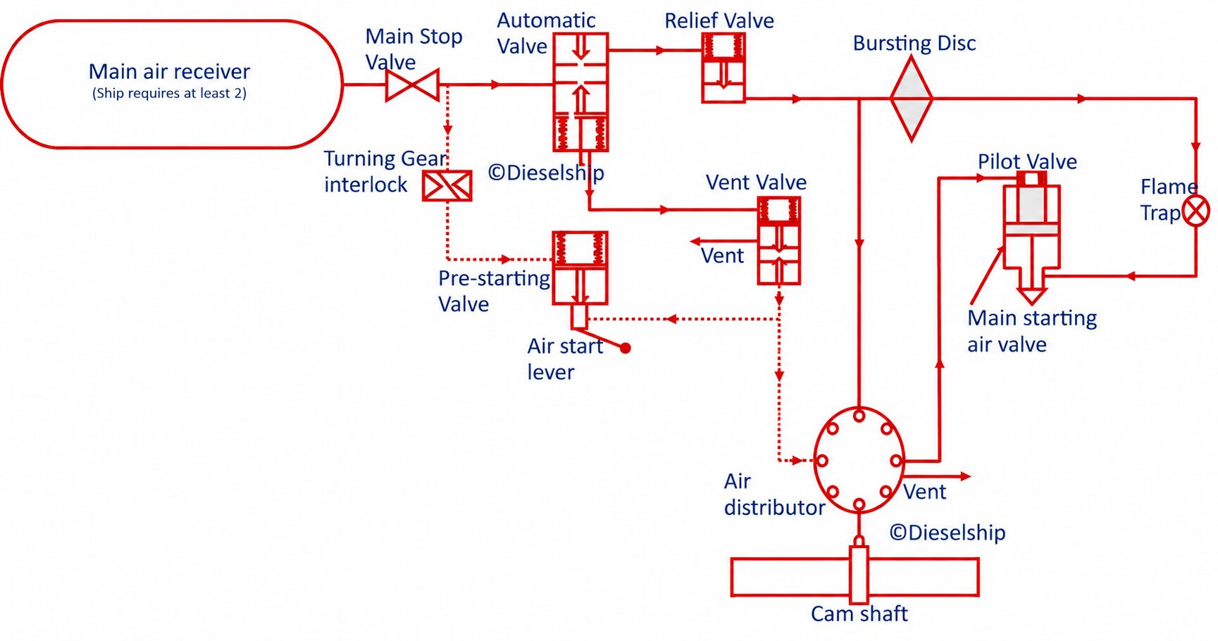
The starting air receivers hold air at about 30 bar. When a start is ordered, the automatic valve (main starting valve) opens and main air fills the manifold up to the starting air valve on each cylinder cover. Nothing enters a cylinder until that cylinder's starting air valve is opened by pilot air from the distributor.
Inside the distributor, one pilot valve per cylinder sits around a cam. While a pilot valve rides on the base of the cam, it passes pilot air to open its cylinder's starting air valve. When the cam lifts it, the pilot air is vented and the spring closes the starting air valve. The cam profile sets the air period, and the pilot valves are spaced around the cam to match the firing order. For astern running the distributor gives the same timing in the astern direction.
Why the cam diagram looks back to front
The timing is often drawn on the distributor cam instead of the crank circle. A cam diagram is drawn from the cam's point of view, so the cylinders run round it in the opposite direction to the crank diagram. For firing order 1-4-3-2 this puts No. 1's air period on the left, with No. 3's TDC directly opposite No. 1's. Drawing it in crank order is a common slip.
Electronically controlled engines
On electronically controlled engines the mechanical distributor is gone. The engine control system reads the crank angle and opens each starting air valve through its own solenoid valve, in firing order, ahead or astern. The timing logic is exactly the same; only the hardware has changed.
Slow turning: the check before the start
Slow turning turns the engine through one revolution on reduced starting air, with no fuel, before a normal start. It proves the engine is free to turn and finds a hydraulic or mechanical lock at low force.
The arrangement
A slow turning valve bypasses the main starting valve (automatic valve) and admits only a small air flow. All the starting interlocks, such as the turning gear interlock, still apply. The air distributor opens the cylinder starting air valves in firing order as in a normal start, but the fuel index is held at zero.
What it protects against
- Hydraulic lock. While the engine is stopped, liquid can collect in a cylinder: cooling water from a cracked liner or cylinder cover, fuel from a leaking fuel valve, lubricating oil, or water from a leaking scavenge air cooler or from exhaust gas boiler washing. Liquid does not compress. A full start against it can bend a connecting rod or piston rod, damage bearings or crack a cover or liner.
- Mechanical lock. A tool or foreign object left in a cylinder or the crankcase after an overhaul.
With the low air flow the piston cannot build enough force to overcome the lock. The engine simply stops against it, undamaged.
The sequence
- A start is ordered after the engine has been stopped longer than the set time, usually about 30 minutes (about 20 minutes on some electronically controlled engines). The time is set in the remote control system.
- The slow turning valve opens instead of the main starting valve. Fuel stays off.
- The engine turns slowly on the distributor timing.
- If it completes one revolution within the set time, the slow turning valve closes and the normal start follows: full air, then fuel.
- If it does not, a slow turning failure alarm is given in the engine control room and the start is stopped.
When preparing for sea, the engine is also turned through one revolution on the slow turning valve with the indicator cocks open, so any liquid is blown out.
If the alarm sounds
Never override it. Close the starting air, engage the turning gear, open the indicator cocks and turn the engine to expel any liquid, noting which cylinder discharges. Find and fix the source before the next start attempt.
Four-stroke standby engines
Large four-stroke engines on standby, such as cruise ship engines and generator engines, are slow turned automatically at set intervals, for example every 2 hours. The main air stop valve stays shut and air passes through a spring-loaded throttle non-return valve set to turn the engine at about 15 to 25 rpm. On electronically controlled engines the slow turning valve is operated through a solenoid valve by a timed function of the engine control system.
Common mistakes in the exam answer
| Mistake | What to write instead |
|---|---|
| Air shown coming on at TDC | Air on about 15° after firing TDC, where the crank has a lever arm |
| No exhaust opening marked | Mark the exhaust opening at 140° ATDC so the 10° margin is visible |
| Four-stroke TDC not identified | Label it firing TDC, the TDC at the end of compression |
| Overlap given as the air period | Overlap is the air period minus the firing interval: 115° minus 90° gives 25° for four cylinders |
| "Four cylinders minimum" with no reason | Show the three-cylinder case: 120° minus 115° leaves a 5° gap |
| Cam diagram drawn in crank order | On the cam the cylinders run the opposite way; for 1-4-3-2, No. 3's TDC is opposite No. 1's |
| Slow turning described as a warm-up | A check for hydraulic and mechanical lock: one revolution, reduced air, no fuel |
Key numbers
- Air on about 15° ATDC, after firing TDC, where the crank has a lever arm.
- Air off about 130° ATDC, 10° before the exhaust opens at 140° ATDC (40° BBDC).
- Air period 115° on a two-stroke, 125° on a four-stroke, whose exhaust opens later at 30° BBDC.
- Overlap is the air period minus the firing interval: 25° on four cylinders, 55° on six, at least 15° in practice.
- Three cylinders leave a 5° gap, so a two-stroke needs at least four cylinders to start on air from any position.
- Slow turning: one revolution on reduced air with no fuel, before a start after about 30 minutes stopped.
Sitting MEO Class 2?
This question appeared in the MMD MEO Class 2 Engineering Knowledge (Motor) paper in December 2025 and again in September 2026: draw and explain a typical starting air timing diagram for a single cylinder (8 marks), explain starting air overlap and why it is necessary in a multi-cylinder engine (4 marks), and describe the slow turning arrangement and its purpose (4 marks).
Dieselship's exam guides work through questions like this one, with diagrams you can reproduce in the exam hall.
Explore Dieselship exam guidesDiagrams © Dieselship. Crank angles are typical teaching values; the actual starting air timing and slow turning settings of any engine are set by its maker. Always follow the maker's instruction manual on board.